
Advanced VRF-Lite Design Considerations
This post explores advanced VRF-Lite design considerations including scalability limits, route leaking patterns, integration with OSPF and HSRP, and security enforcement at VRF boundaries. It targets experienced engineers building multi-tenant or compliance-driven network segments using VRF-Lite wi

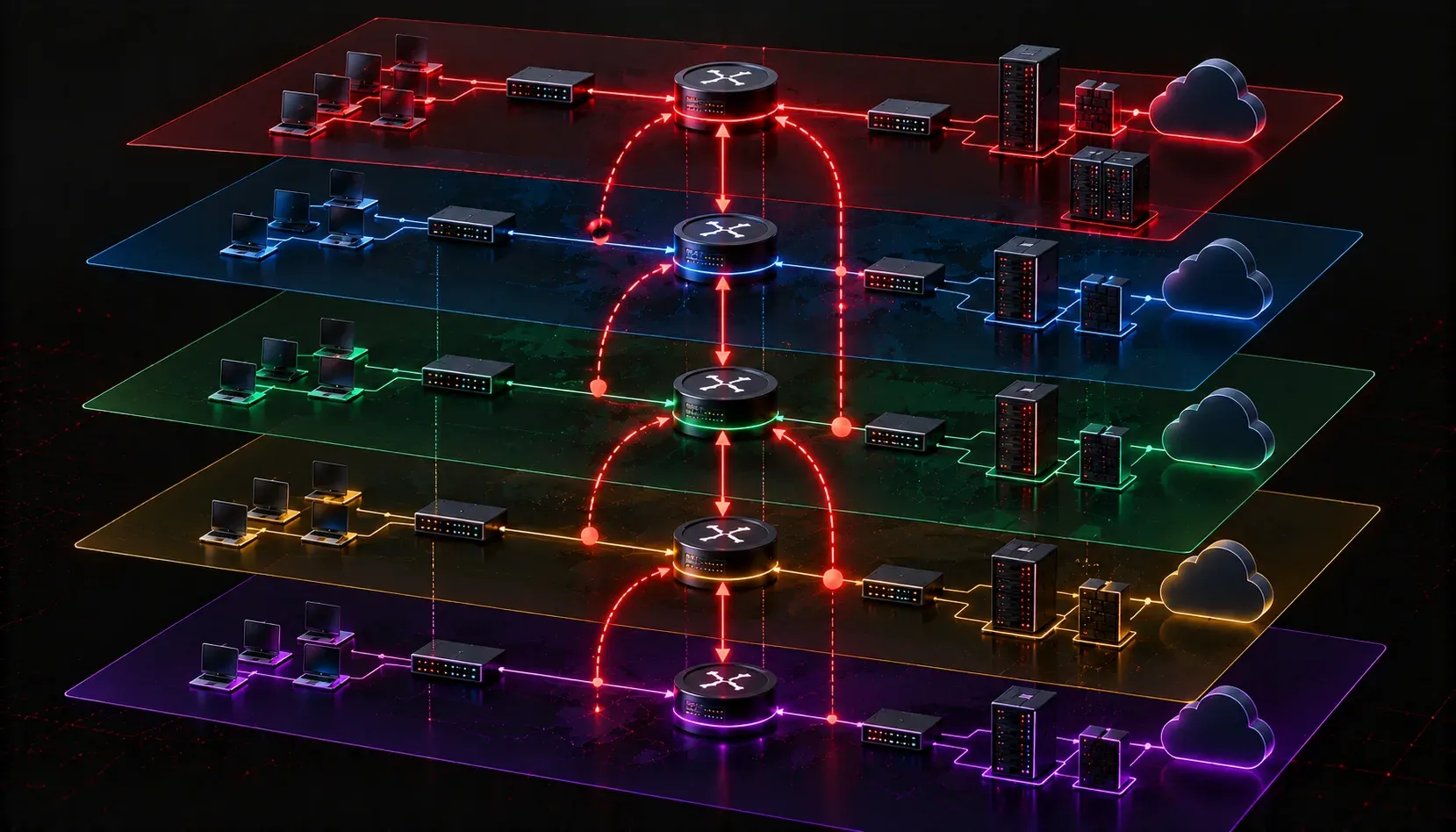
VRF-Lite gets introduced early in most routing curricula as a way to achieve traffic separation without a full MPLS backbone. But production deployments surface design decisions that go well beyond the basics of assigning interfaces to VRFs and redistributing routes. If you are building multi-tenant infrastructure, segmented campus networks, or regulated environments where traffic isolation is a compliance requirement, the design choices you make with VRF-Lite have real consequences for scalability, security posture, and operational complexity.
Scalability Limits You Will Hit in Production
VRF-Lite scalability is constrained at several layers. The first is the routing table ceiling per VRF. Each VRF maintains an independent RIB, which means memory consumption scales linearly with the number of VRFs multiplied by the number of prefixes per VRF. On a Catalyst 9300 or 9500 series switch, you are working within shared TCAM and memory budgets across all VRFs and the global table. Monitor this actively using show platform resources and show ip route summary vrf <name>.
The second constraint is inter-VRF routing complexity. Every inter-VRF communication path requires either route leaking or a dedicated firewall/service node. Route leaking via import map and export map under the VRF address-family configuration is powerful but creates a tangled dependency graph at scale. If you have 20 VRFs with selective route sharing, you will be managing a matrix of import/export policies that becomes extremely difficult to audit.
A practical ceiling for VRF-Lite deployments on a single device is typically in the range of 50 to 100 VRFs before you start seeing operational complexity outpace the benefits. Beyond that threshold, evaluate whether a full MPLS L3VPN architecture makes more sense, particularly if you have PE routers already running BGP.
Route Leaking: Design Patterns and Pitfalls
Selective route leaking between VRFs is where most advanced VRF-Lite designs get complicated. The standard mechanism uses BGP route targets combined with VRF import and export maps. A shared services VRF pattern, for example, allows specific prefixes from a central services segment to be imported into tenant VRFs without full mutual reachability.
ip vrf SHARED-SERVICES
 rd 65000:100
 route-target export 65000:100
 route-target import 65000:100

ip vrf TENANT-A
 rd 65000:200
 route-target export 65000:200
 route-target import 65000:200
 route-target import 65000:100
In this pattern, TENANT-A imports routes from SHARED-SERVICES, but SHARED-SERVICES does not import TENANT-A routes. This gives you one-directional reachability: tenant hosts can reach shared services, but shared services infrastructure cannot initiate connections into the tenant segment. This is a critical network security design consideration for environments like PCI-DSS or HIPAA where lateral movement from shared infrastructure into regulated segments must be prevented.
The pitfall here is asymmetric routing. If the shared services host initiates a return path through the global table or a different VRF, you create routing loops or dropped sessions. Always verify bidirectional forwarding behavior with traceroute vrf <name> <destination> and confirm the return path is consistent with your intent.
Design Integration with Other Technologies
Advanced VRF-Lite design rarely exists in isolation. You will need to integrate it with several other technologies, and each introduces its own configuration requirements.
OSPF with VRF-Lite
Each VRF runs a separate OSPF process. You cannot share a single OSPF process across VRFs. This means process IDs must be tracked carefully, and redistribution between OSPF processes and BGP must be explicit. Use the vrf keyword when configuring the OSPF process:
router ospf 10 vrf TENANT-A
 network 10.10.0.0 0.0.255.255 area 0
Redistribution between the VRF OSPF process and the MP-BGP process that handles route target exchange is the standard integration point. This is where incorrect metric settings or missing redistribution statements create black holes that are non-obvious to troubleshoot.
HSRP and First-Hop Redundancy
HSRP groups must be unique per VRF per interface. In multi-tenant switched environments where multiple VRFs terminate on SVIs across a stack or VSS pair, group number collisions are a real operational hazard. Establish a naming convention and numbering scheme before deployment, not after. Map HSRP group numbers to VLAN IDs or VRF identifiers systematically.
NetFlow and Telemetry
Flow monitoring in VRF-Lite environments requires VRF-aware NetFlow configuration. If your collector does not receive VRF context in the flow records, traffic attribution across tenants becomes impossible. Use flexible NetFlow with the vrf option on the flow monitor assignment:
interface GigabitEthernet1/0/1
 ip vrf forwarding TENANT-A
 ip flow monitor MONITOR-1 input vrf TENANT-A
Security Considerations at Scale
VRF-Lite provides logical separation, not cryptographic isolation. A misconfigured route leak, an ACL gap on a inter-VRF service node, or a bug in the platform's FIB programming can create cross-VRF reachability that violates your segmentation intent. Treat VRF boundaries as trust boundaries and enforce them with ACLs at the inter-VRF routing point, not just with routing policy alone.
For environments where regulatory compliance requires demonstrable traffic separation, document your route leak matrix explicitly and validate it with periodic reachability tests from each VRF. Automation here pays dividends: a simple Netmiko-based script that runs ping vrf from each segment to a matrix of targets and logs the results gives you auditable evidence of isolation.
Also review control plane exposure. Management plane access, SNMP, and SSH should be bound to a dedicated management VRF. Use ip ssh source-interface and snmp-server source-interface pointing at an interface in the management VRF to prevent control plane access from data-plane VRFs.
Troubleshooting Framework
When traffic is not flowing as expected in a VRF-Lite deployment, work through this sequence:
- Confirm the interface is assigned to the correct VRF with
show ip vrf interfaces. - Verify the VRF RIB has the expected prefixes with
show ip route vrf <name>. - Check CEF for the VRF with
show ip cef vrf <name> <prefix> detailto confirm FIB programming matches the RIB. - Validate route target import/export with
show bgp vpnv4 unicast vrf <name>and confirm RT values match your design intent. - If using route leaking, confirm the leaked prefix appears in the destination VRF's RIB and that the next-hop is reachable within that VRF's forwarding context.
Recommended Reading
For exam-level depth on VRF-Lite and its integration with advanced routing technologies, the Cisco Press CCNP Enterprise Advanced Routing ENARSI 300-410 Official Cert Guide by Raymond Lacoste covers the configuration and troubleshooting scenarios you will encounter both on the exam and in production deployments.
What's Next
With a solid understanding of advanced VRF-Lite design, the logical next step is exploring how these same segmentation principles scale across a service provider backbone using MPLS Layer 3 VPNs. The transition from VRF-Lite to a full L3VPN architecture with PE-CE routing protocols and route distinguisher design is where the ENARSI exam pushes you into provider-edge configuration territory.
Tools and resources for this topic
- CCNP ENARSI 300-410 Official Cert Guide — The definitive ENARSI study resource by Raymond Lacoste. Covers advanced routing, services, and troubleshooting.