
What is Rapid PVST+ and How Does it Work?
Rapid PVST+ prevents network loops by running separate spanning tree instances for each VLAN, providing fast convergence and load balancing. This protocol elects root bridges per VLAN and assigns port roles to maintain loop-free topologies while keeping backup paths ready.

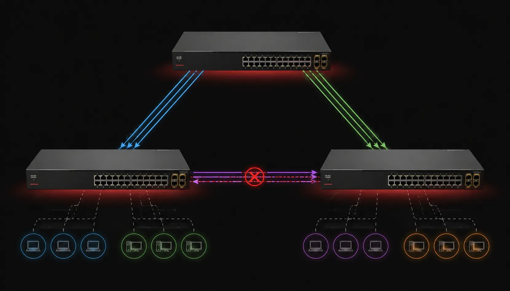
Network loops can bring your entire network to its knees in seconds. When you have multiple paths between switches (which is great for redundancy), you also create the potential for broadcast storms and MAC address table corruption. This is where Rapid PVST+ comes to the rescue.
What is Rapid PVST+?
Rapid PVST+ (Rapid Per-VLAN Spanning Tree Plus) is Cisco's implementation of spanning tree protocol based on the IEEE 802.1w (RSTP) standard with Cisco-specific enhancements. It prevents network loops while maintaining separate spanning tree instances for each VLAN. Think of it as having a dedicated traffic director for each VLAN, ensuring packets take the best path while keeping backup routes ready for instant activation.
The "Rapid" part means convergence happens in seconds rather than the 30-50 seconds required by traditional spanning tree protocols. This speed is crucial in modern networks, where even a few seconds of downtime can impact user experience.
How Rapid PVST+ Differs from Standard RSTP
While both Rapid PVST+ and standard RSTP (IEEE 802.1w) provide fast convergence, there are key differences:
- Per-VLAN Instances: Standard RSTP runs one spanning tree instance for all VLANs, while Rapid PVST+ creates separate instances for each VLAN
- Load Balancing: Rapid PVST+ enables different root bridges per VLAN, allowing traffic distribution across multiple links
- VLAN Awareness: BPDUs in Rapid PVST+ carry VLAN information, while standard RSTP BPDUs do not
- Cisco Enhancements: Additional features like BPDU Guard, Root Guard, and enhanced PortFast functionality
Why Do We Need Spanning Tree Protocols?
Consider a simple network with three switches connected in a triangle. Without spanning tree:
- A broadcast frame enters the loop and circulates endlessly
- Each switch forwards the frame to all other ports
- The frame multiplies exponentially, consuming all available bandwidth
- Switch MAC address tables become corrupted as they see the same MAC address on multiple ports
Spanning tree protocols solve this by mathematically calculating a loop-free topology, temporarily blocking certain ports to break loops while keeping them as standby links.
How Rapid PVST+ Works
Root Bridge Election
For each VLAN, switches elect a root bridge using Bridge Protocol Data Units (BPDUs). The switch with the lowest bridge ID becomes the root. The bridge ID combines:
- Bridge priority (default 32768) + VLAN ID
- MAC address (used as tiebreaker)
You can verify the root bridge with:
Switch# show spanning-tree vlan 10
VLAN0010
  Spanning tree enabled protocol rstp
  Root ID    Priority    32778
             Address     0019.068d.6980
             This bridge is the root
Port Roles and States
Rapid PVST+ assigns each port a specific role:
- Root Port: Best path to the root bridge
- Designated Port: Forwarding port on each network segment
- Alternate Port: Backup to the root port
- Backup Port: Backup to a designated port
Port states are simplified compared to traditional STP:
- Discarding: Not forwarding frames, not learning MAC addresses
- Learning: Not forwarding frames, but learning MAC addresses
- Forwarding: Fully operational
Rapid Convergence Features
What makes Rapid PVST+ fast?
- Edge Ports: Ports connected to end devices transition immediately to forwarding
- Point-to-Point Links: Direct switch-to-switch connections converge rapidly
- Proposal/Agreement Process: Switches negotiate topology changes quickly
Configure an edge port (connected to end devices) with:
Switch(config)# interface fastethernet 0/1
Switch(config-if)# spanning-tree portfast
PVST+ vs Standard STP
Traditional STP runs one instance for all VLANs, which means:
- All VLANs follow the same topology
- No load balancing between VLANs
- Suboptimal path utilization
Rapid PVST+ creates separate spanning tree instances per VLAN, allowing:
- Different root bridges for different VLANs
- Load balancing across multiple uplinks
- Better bandwidth utilization
Basic Configuration Example
Here's how to configure Rapid PVST+ with different root bridges for load balancing:
# On Switch A - Make it root for VLANs 10-20
Switch-A(config)# spanning-tree vlan 10-20 priority 4096

# On Switch B - Make it root for VLANs 30-40
Switch-B(config)# spanning-tree vlan 30-40 priority 4096

# Enable Rapid PVST+ (usually default on modern switches)
Switch(config)# spanning-tree mode rapid-pvst
Monitor the results:
Switch# show spanning-tree summary
Switch is in rapid-pvst mode
Root bridge for: VLAN0010, VLAN0020
Extended system ID is enabled
Portfast Default is disabled
What's Next
Now that you understand how Rapid PVST+ prevents loops and provides per-VLAN optimization, you're ready to dive deeper into spanning tree troubleshooting and advanced features like MST (Multiple Spanning Tree). In our next post, we'll explore common spanning tree problems and how to diagnose them using show commands and debug outputs.
Tools and resources for this topic
- CCNA Official Cert Guide (Wendell Odom) — The definitive CCNA study resource. Both volumes cover the 200-301 exam blueprint in full.
- Wendell Odom CCNA Vol 1 — Covers networking fundamentals, switching, and routing basics.
- Wendell Odom CCNA Vol 2 — Covers advanced routing, WAN, infrastructure services, and security.