
How to Use Patch Cables with Network Diagrams
Learn how to use network diagrams to properly connect devices with patch cables. This beginner-friendly guide covers cable types, step-by-step connection processes, and essential troubleshooting tips for successful network setups.

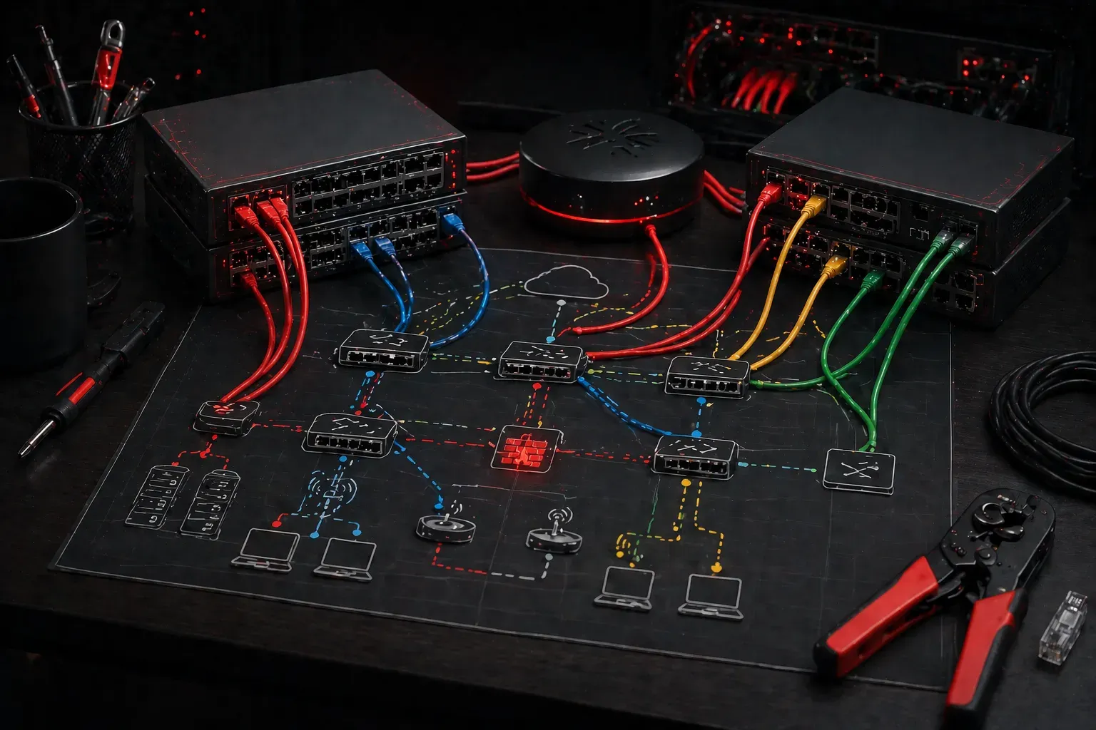
Understanding Network Diagrams and Cable Connections
Network diagrams are your roadmap to successful cable connections. When you're starting out with networking, these visual guides show exactly where each patch cable goes and why it matters. Think of a network diagram as a blueprint that prevents costly mistakes and saves you hours of troubleshooting.
A typical network diagram uses standardized symbols: rectangles for switches, circles for routers, and lines representing cable connections. Each line should be labeled with the cable type and port numbers, making it crystal clear which devices connect to each other.
Essential Cable Types for Your Network Setup
Before diving into connections, you need to understand the basic cable types you'll encounter:
- Straight-through cables: Connect different device types (computer to switch, switch to router)
- Crossover cables: Connect similar device types (switch to switch, router to router)
- Console cables: Used for initial device configuration
Modern devices often have auto-MDI/MDIX capability, which automatically detects the correct cable type needed. However, understanding these basics helps you troubleshoot older equipment and builds foundational knowledge.
Step-by-Step Cable Connection Process
When using patch cables with your network diagram, follow this systematic approach:
Step 1: Prepare Your Workspace
Start by printing your network diagram and gathering all necessary cables. Label each cable with masking tape showing the source and destination ports. This simple step prevents confusion in complex setups.
Step 2: Power Down Devices
Always power down network devices before making cable connections. This protects both the equipment and prevents network disruptions during the connection process.
Step 3: Connect in Logical Order
Begin with core infrastructure first. Connect your router to the main switch, then branch out to access switches. This approach ensures your network backbone is solid before adding endpoints.
Example connection sequence:
1. ISP modem → Router WAN port
2. Router LAN port → Core switch port 1
3. Core switch port 2 → Access switch uplink port
4. Access switch ports → End devices
Step 4: Verify Physical Connections
Check each cable connection against your diagram. Ensure cables click securely into ports and LED indicators show link activity. Most switches display green lights for good connections and amber for link issues.
Common Beginner Tips for Success
Here are essential beginner tips that will make your cable management much smoother:
- Cable management: Use velcro ties to bundle cables neatly. Avoid sharp bends that can damage internal wires.
- Documentation: Update your diagram if you make any changes during installation. Future troubleshooting depends on accurate documentation.
- Testing: Use a cable tester to verify each connection before powering up devices. This catches wiring issues early.
- Spare cables: Keep extra patch cables of common lengths (1ft, 3ft, 6ft) for quick replacements.
Power Connections and Safety
Your network diagram should also indicate power requirements. Most switches and routers use standard AC adapters, but enterprise equipment might require specific power considerations:
- Check voltage requirements before connecting power
- Use UPS systems for critical network infrastructure
- Plan power cable routing to avoid interference with data cables
- Label power adapters to match their corresponding devices
Troubleshooting Cable Connection Issues
When connections don't work as expected, follow this diagnostic process:
- Verify the cable is fully seated in both ports
- Check link lights on both connected devices
- Try a different cable to eliminate cable faults
- Confirm you're using the correct ports as shown in your diagram
- Review device configuration if physical connections appear correct
Remember, most connection issues stem from simple oversights rather than complex technical problems. Taking time to methodically check each connection point usually resolves the issue quickly.
What's Next
Now that you understand how to use patch cables with network diagrams, the next step is learning about rack layout basics and proper cable management in network closets. This knowledge helps you scale from small desktop setups to professional network installations.