
Configuring GRE and IPsec Tunnels for Secure Data Paths
Comprehensive guide to configuring GRE and IPsec tunnels for secure enterprise connectivity. Covers implementation details, routing integration, and troubleshooting for CCNP ENCOR exam objectives.

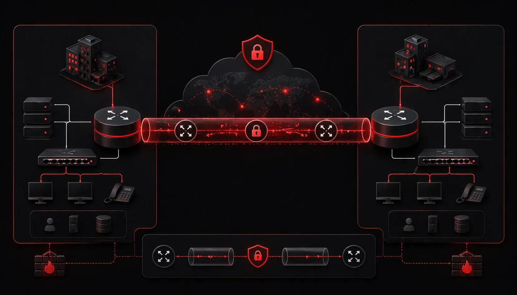
GRE and IPsec tunnels form the backbone of secure site-to-site connectivity in enterprise networks. While GRE provides the encapsulation mechanism for routing protocols and multicast traffic, IPsec delivers the encryption and authentication needed for production environments. Understanding how to configure both technologies together creates robust, scalable VPN solutions that support dynamic routing and maintain security posture across WAN links.
GRE Fundamentals for ENCOR
Generic Routing Encapsulation creates a virtual point-to-point link by encapsulating Layer 3 protocols within IP packets. The key advantage lies in its ability to transport routing protocol updates, multicast traffic, and non-IP protocols across IP-only networks. GRE adds a 24-byte header (20-byte IP + 4-byte GRE) to each packet, creating overhead that must be considered in MTU calculations.
Basic GRE tunnel configuration requires defining source and destination interfaces, tunnel addresses, and routing:
interface Tunnel0
 ip address 10.1.1.1 255.255.255.252
 tunnel source GigabitEthernet0/0
 tunnel destination 203.0.113.2
 tunnel mode gre ip
The tunnel source can reference either an interface or IP address. Using an interface provides automatic source address selection if the interface has multiple addresses configured.
IPsec Deployment Architecture
IPsec operates in two modes: transport and tunnel. Transport mode encrypts only the payload of the original IP packet, leaving the original IP header intact and adding IPsec headers. Tunnel mode encrypts the entire original IP packet and adds a new IP header along with IPsec headers, providing more security but with additional overhead.
For GRE over IPsec deployments, transport mode encrypts the GRE payload while preserving the original IP header structure. This approach reduces overhead compared to tunnel mode, which encapsulates the entire original packet.
IPsec configuration involves three components: ISAKMP policies for Phase 1 negotiation, IPsec transform sets defining encryption algorithms, and crypto maps binding policies to interfaces.
Phase 1 ISAKMP Configuration
crypto isakmp policy 10
 encr aes 256
 hash sha256
 authentication pre-share
 group 14
 lifetime 86400

crypto isakmp key cisco123 address 203.0.113.2
Phase 1 establishes a secure management connection using Internet Key Exchange (IKE). The policy defines encryption strength, hashing algorithms, authentication method, and Diffie-Hellman group for key exchange.
Phase 2 Transform Set Configuration
crypto ipsec transform-set STRONG esp-aes 256 esp-sha256-hmac
 mode transport

crypto map VPN-MAP 10 ipsec-isakmp
 set peer 203.0.113.2
 set transform-set STRONG
 match address VPN-TRAFFIC
The transform set specifies encryption and authentication protocols for actual data transmission. Transport mode specifically protects GRE tunnels without additional IP header overhead.
GRE over IPsec Implementation
Combining GRE with IPsec requires careful configuration sequencing. The GRE tunnel must be established first, followed by IPsec protection of the tunnel traffic. Here's a complete site-to-site configuration:
! Access list defining GRE traffic for encryption
ip access-list extended VPN-TRAFFIC
 permit gre host 198.51.100.1 host 203.0.113.2

! GRE tunnel configuration
interface Tunnel0
 ip address 10.1.1.1 255.255.255.252
 tunnel source 198.51.100.1
 tunnel destination 203.0.113.2
 tunnel mode gre ip

! Apply crypto map to physical interface
interface GigabitEthernet0/0
 ip address 198.51.100.1 255.255.255.0
 crypto map VPN-MAP

! Routing through tunnel
ip route 192.168.2.0 255.255.255.0 Tunnel0
The access list must specifically permit GRE protocol (47) between tunnel endpoints. Static routing or dynamic routing protocols can operate over the tunnel interface once established.
Dynamic Routing Integration
GRE tunnels support routing protocol adjacencies, enabling dynamic path selection and automatic failover. OSPF configuration over GRE requires network type consideration:
interface Tunnel0
 ip ospf network point-to-point
 ip ospf hello-interval 10
 ip ospf dead-interval 40

router ospf 1
 network 10.1.1.0 0.0.0.3 area 0
 network 192.168.1.0 0.0.0.255 area 0
Point-to-point network type eliminates DR/BDR election overhead and provides faster convergence on tunnel links.
Advanced Configuration Considerations
MTU and MSS Optimization
GRE and IPsec overhead requires MTU adjustments to prevent fragmentation. Calculate the effective MTU by subtracting encapsulation overhead from the physical interface MTU. IPsec overhead varies based on the specific encryption and authentication algorithms used, typically ranging from 24-60 bytes depending on the cipher suite and authentication method:
interface Tunnel0
 ip mtu 1436
 ip tcp adjust-mss 1396
Standard Ethernet MTU (1500) minus GRE overhead (24) minus IPsec overhead (typically 40-60 bytes for ESP with AES and SHA) equals approximately 1420-1436 bytes. TCP MSS should be 40 bytes less than tunnel MTU. It's critical to match MTU settings on both ends of the tunnel to prevent fragmentation issues.
Keepalive and Monitoring
GRE keepalives detect tunnel failures and trigger routing protocol convergence:
interface Tunnel0
 keepalive 5 3
 ip ospf dead-interval minimal hello-multiplier 3
Keepalive packets sent every 5 seconds with 3-retry failure detection provide rapid failure detection independent of routing protocol timers.
Verification and Troubleshooting
Multiple verification commands confirm tunnel operation and security association status:
Router# show crypto isakmp sa
IPv4 Crypto ISAKMP SA
dst          src          state        conn-id  status
203.0.113.2  198.51.100.1 QM_IDLE      1001     ACTIVE

Router# show crypto ipsec sa
interface: GigabitEthernet0/0
    Crypto map tag: VPN-MAP, local addr 198.51.100.1
   protected vrf: (none)
   local  ident (addr/mask/prot/port): (198.51.100.1/255.255.255.255/47/0)
   remote ident (addr/mask/prot/port): (203.0.113.2/255.255.255.255/47/0)
The show interface tunnel0 command displays tunnel status, while show ip route confirms routing through the tunnel interface.
Common Issues and Resolution
Tunnel flapping often results from MTU mismatches or keepalive failures. Use debug tunnel and debug crypto isakmp for detailed troubleshooting. Ensure both endpoints have matching IPsec policies and that firewall rules permit GRE and IPsec traffic (protocols 47, UDP 500, and UDP 4500).
What's Next
With GRE and IPsec tunnel fundamentals established, the next logical progression involves exploring DMVPN architecture. Dynamic Multipoint VPN builds upon these concepts to create scalable hub-and-spoke networks with spoke-to-spoke capabilities, representing a critical evolution in enterprise WAN design covered extensively in ENCOR objectives.
Tools and resources for this topic
- CCNP ENCOR 350-401 Official Cert Guide — The definitive ENCOR study resource by Brad Edgeworth. Covers enterprise infrastructure, virtualisation, and automation.