Connecting Switches and Routers: A Beginner's Guide
This guide explains how to physically connect switches and routers in small network topologies, covering cable types, basic layouts, and power considerations for beginners.

Understanding Network Connections: The Foundation
Learning to connect switches and routers is like understanding how different components in a system work together to achieve a common goal. Just as a water distribution system uses pipes, valves, and pumps to deliver water throughout a building, network switches and routers work together to move data around your network. Let's break down these basic connections step by step.
The Key Players in Your Network
Before we connect anything, let's understand what we're working with:
- Switches: Think of these as smart hubs that connect devices in the same network (like computers, printers, and phones)
- Routers: These are like traffic directors that connect different networks together and provide internet access
- Patch cables: The physical connections that carry network data between devices
Choosing the Right Patch Cables
Not all cables are created equal. For basic connections between switches and routers, you'll primarily use:
- Straight-through cables: Used to connect different types of devices (switch to router, computer to switch)
- Crossover cables: Used to connect similar devices (switch to switch, router to router)
Many modern devices support auto-MDIX, which means the device automatically detects and adjusts for the cable type. However, it's important to verify that your specific equipment supports this feature, as some older or specialized models may not have auto-MDIX capability.
Basic Network Topology: Small Office Setup
Let's walk through connecting a simple small office network. Imagine you're setting up a coffee shop with internet, a few computers, and a wireless access point.
Step 1: Connect the Internet Source
Start with your internet connection from your ISP (Internet Service Provider). This typically connects to the WAN or Internet port on your router using an Ethernet cable.
Internet (ISP) → Router WAN PortStep 2: Connect the Router to Your Switch
Use a straight-through Ethernet cable to connect one of the router's LAN ports to any port on your switch. This gives all devices connected to the switch access to the internet through the router.
Router LAN Port → Switch Port (any available port)Step 3: Connect Your Devices
Now connect your end devices to the remaining switch ports:
- Computers to switch ports
- Printers to switch ports
- Wireless access points to switch ports
Physical Installation: Power and Rack Layout Basics
Proper physical setup is crucial for reliable network operations. Here are the essentials:
Power Considerations
- Use surge protectors: Network equipment is sensitive to power fluctuations
- Plan for redundancy: Consider UPS (Uninterruptible Power Supply) units for critical equipment
- Power on sequence: Start with switches, then routers, then end devices
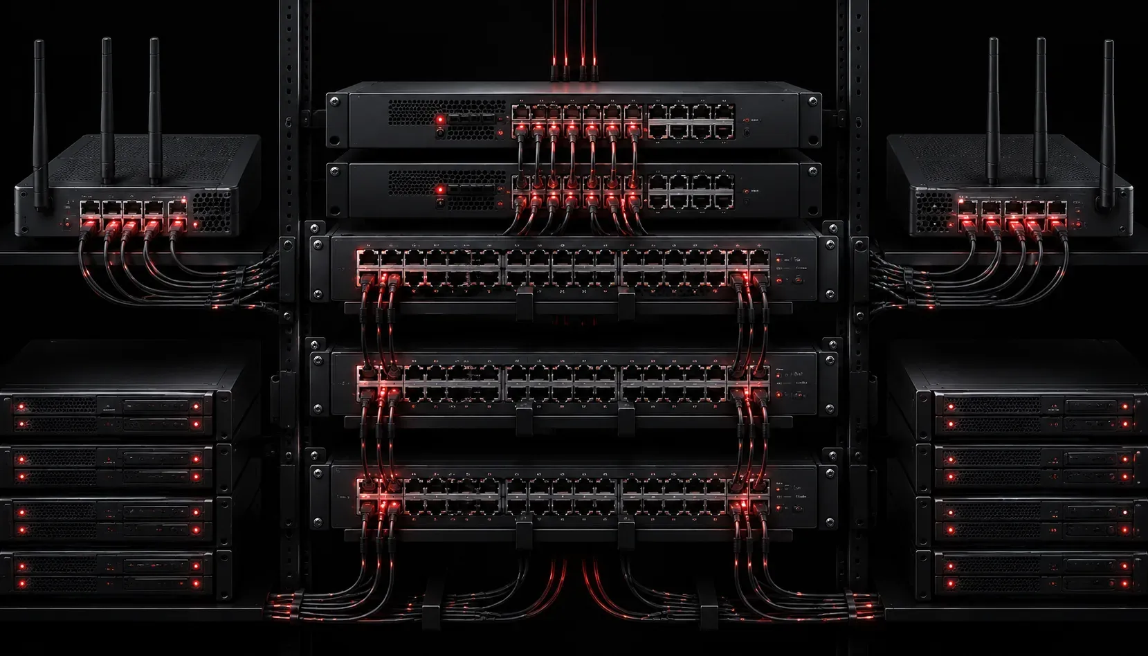
Basic Rack Layout
Even in small installations, organization matters:
- Mount heavier equipment (like UPS units) at the bottom
- Place switches in the middle for easy cable management
- Keep patch panels and cable management at eye level
- Leave space for airflow between devices
Verifying Your Connections
After making your physical connections, verify everything is working:
- Check that all device power LEDs are solid (not blinking)
- Verify link lights on the switch and router ports are green/solid
- Test connectivity from an end device by pinging the router's IP address
A typical verification command from a computer would be:
ping 192.168.1.1This tests connectivity to your router (assuming it uses the common default IP of 192.168.1.1).
Common Connection Mistakes to Avoid
- Using damaged cables: Always test cables before permanent installation
- Mixing up WAN and LAN ports: The WAN port connects to your ISP, LAN ports connect to your internal network
- Forgetting about cable length limits: Ethernet cables should not exceed 100 meters (328 feet)
- Poor cable management: Tangled cables make troubleshooting difficult later
What's Next
Now that you understand the physical connections, you'll want to learn about configuring these devices with proper IP addresses and basic security settings. In our next post, we'll cover basic switch and router configuration using the command line interface, including setting up VLANs (Virtual Local Area Networks, which allow you to logically separate network segments) and basic routing protocols (the rules that determine how data moves between networks).