
Understanding the OSI Model with Real Examples
A comprehensive walkthrough of the OSI model's 7 layers with real-world examples, showing exactly what headers get added at each layer and how devices operate at different levels. Covers encapsulation process and maps theoretical concepts to practical networking scenarios.

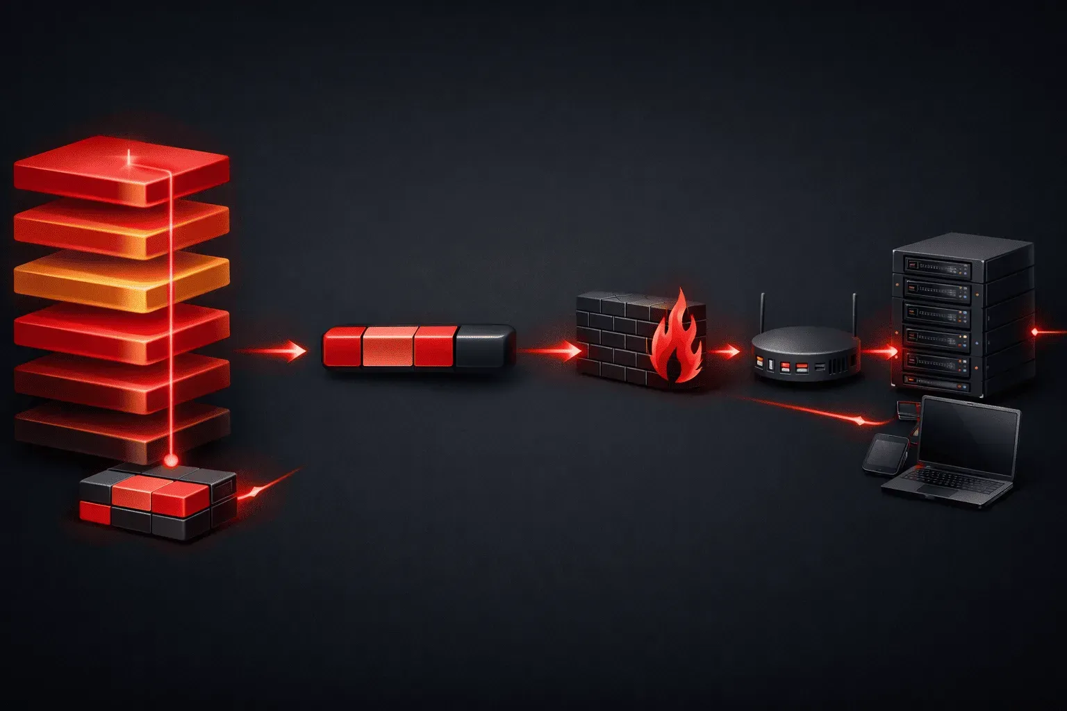
The OSI (Open Systems Interconnection) model is networking's most fundamental framework, breaking communication into seven distinct layers. While it might seem abstract at first, understanding how real data flows through these layers will make networking concepts click into place. Let's walk through each layer with concrete examples and see exactly what happens to your data.
Layer 1: Physical Layer - The Foundation
The Physical layer deals with the actual transmission medium - cables, wireless signals, and electrical impulses. When you plug an Ethernet cable into your laptop, you're working at Layer 1.
Real Example: Your network card converts digital bits into electrical signals that travel over copper wire. A 1 might be represented by +5 volts, while a 0 is 0 volts. Devices like hubs and repeaters operate here, simply amplifying signals without understanding the data.
What gets added: No headers - just raw bits converted to physical signals.
Layer 2: Data Link Layer - Local Delivery
The Data Link layer handles communication between devices on the same network segment. This is where MAC addresses live.
Real Example: When your computer sends data to your router, it wraps the information in an Ethernet frame with source and destination MAC addresses. Switches operate at this layer, maintaining MAC address tables to forward frames efficiently.
What gets added: Ethernet header containing source MAC, destination MAC, and frame type, plus a trailer with error-checking information.
Ethernet Header: [Dest MAC][Source MAC][Type][Payload][FCS]Layer 3: Network Layer - Routing Across Networks
The Network layer enables communication between different networks using logical addressing. IP addresses operate here.
Real Example: When you visit google.com, your router examines the destination IP address (like 8.8.8.8) and determines the best path to reach that network. Routers make forwarding decisions based on Layer 3 information.
What gets added: IP header with source and destination IP addresses, TTL (Time To Live), protocol type, and other routing information.
IP Header: [Version][Header Length][Type of Service][Total Length]
          [ID][Flags][Fragment Offset][TTL][Protocol][Checksum]
          [Source IP][Destination IP][Options]
Layer 4: Transport Layer - Reliable Delivery
The Transport layer ensures data arrives completely and in order. TCP and UDP protocols operate here.
Real Example: When downloading a file, TCP breaks it into segments, numbers them sequentially, and ensures your computer acknowledges receipt of each piece. If segment 47 gets lost, TCP will retransmit only that segment.
What gets added: TCP header with source/destination port numbers, sequence numbers, acknowledgment numbers, and control flags.
TCP Header: [Source Port][Dest Port][Sequence Number]
           [Acknowledgment Number][Flags][Window Size]
           [Checksum][Urgent Pointer][Options]
Layer 5: Session Layer - Managing Conversations
The Session layer establishes, manages, and terminates communication sessions between applications.
Real Example: When you log into a website, the session layer maintains your authentication state. If your connection drops temporarily, it can resume the session without requiring you to log in again. NetBIOS and RPC operate at this layer.
What gets added: Session control information for establishing, maintaining, and terminating connections.
Layer 6: Presentation Layer - Data Translation
The Presentation layer handles data formatting, encryption, and compression.
Real Example: When you visit an HTTPS website, SSL/TLS encryption occurs at this layer. Your browser also handles JPEG image decompression and character encoding (like UTF-8) here. The data gets translated into a format the application can understand.
What gets added: Encryption headers, compression information, and format specifications.
Layer 7: Application Layer - User Interface
The Application layer provides network services directly to end users and applications.
Real Example: When you send an email, SMTP (Simple Mail Transfer Protocol) operates at Layer 7. Your email client communicates with the mail server using application-specific commands like HELO, MAIL FROM, and RCPT TO.
What gets added: Application-specific headers and data, such as HTTP headers for web browsing or SMTP commands for email.
Encapsulation in Action
As data moves down the OSI layers, each layer adds its own header information - a process called encapsulation. When you send a web request:
- Layer 7: HTTP request created
- Layer 4: TCP header added (creating a segment)
- Layer 3: IP header added (creating a packet)
- Layer 2: Ethernet header added (creating a frame)
- Layer 1: Frame converted to electrical signals
The receiving device reverses this process, stripping headers at each layer until the original HTTP request reaches the web server.
What's Next
Now that you understand how the OSI model maps to real network communication, our next post will dive deep into TCP/IP protocols and how they differ from the theoretical OSI model. You'll learn why we often talk about the "TCP/IP stack" in practical networking scenarios.