
How to Build Your First Network Lab in Cisco Packet Tracer

If you are studying for your CCNA or just getting started with networking, Cisco Packet Tracer is the tool you will spend a lot of time in. It is free, it runs on your laptop, and it lets you build and test networks without touching a single physical device. In this guide we are going to walk through building your very first network from scratch – routers, switches, PCs, cabling, IP addresses, and a successful ping to prove it all works.
The Packet Tracer file used in the video above is available to download from the lab challenge page. Follow along here, follow along in the video, or do both. By the end you will have a working two-router network and a solid understanding of why each step matters.
What We Are Building
The topology is deliberately simple. Simple is good when you are learning because every device and every cable has a reason to be there, and you will understand all of them by the time you finish.
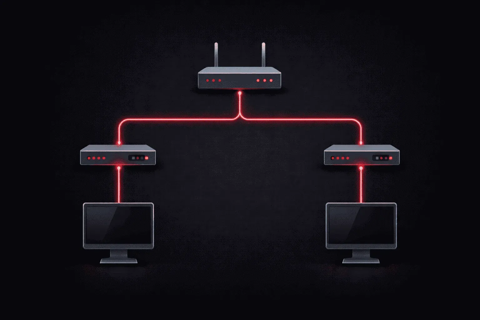
Here is what the finished network looks like:
- One Cisco 4331 router
- Two Cisco 2960 switches (one per side)
- Two PCs (PCA and PCB)
- PCA connects to Switch 1, which connects to the router on Gig 0/0/0
- PCB connects to Switch 2, which connects to the router on Gig 0/0/1
- PCA sits on the 192.168.1.0/24 network
- PCB sits on the 192.168.2.0/24 network
- The router acts as the gateway between both networks
The goal: ping from PCA to PCB across the router. When that works, you have built a functioning routed network.
Step 1: Place Your Devices
Open Packet Tracer and head to the device panel at the bottom left. You need three types of devices.
Start with the router. Click on Network Devices, select Routers, and drag a 4331 onto the canvas. Give it some room -- you want space to add switches and PCs on either side without everything feeling cramped.
Next, grab two switches. Click Switches and select the 2960. This is a Layer 2 switch, which is exactly what you need here. You do not need Layer 3 switching capability for this topology, so do not overcomplicate it. Place one switch to the left of the router and one to the right.
Finally, add two PCs. Click End Devices and drag a PC to the far left (this will be PCA) and another to the far right (this will be PCB). Take a moment to arrange everything so the layout makes visual sense -- left PC, left switch, router in the middle, right switch, right PC. A clean layout makes cabling easier to follow and reduces mistakes.
Step 2: Cable Everything Together -- and Why Manual Beats Automatic
This is where a lot of beginners run into their first problem, and it is worth spending time on.
Down in the bottom panel you will see a Connections section. There is an automatic connection option -- the lightning bolt icon -- that will connect devices for you without asking which interface you want to use. It sounds convenient. It is not.
Here is the problem. When you use automatic connections, Packet Tracer decides which interfaces to use. In testing, it will happily plug the switch into the router's Fast Ethernet 0/1 interface rather than a Gigabit Ethernet interface. Fast Ethernet is a 100 Mbps interface. The router has Gigabit Ethernet interfaces available. You want to use those. On top of that, you have no visibility into which interface was chosen unless you hover over the cable -- and if the interface is still in a shutdown state (which router interfaces are by default), you may not even see that.
Use manual connections. Always.
Select the Copper Straight-Through cable from the connections panel. Now cable the network like this:
- PCA FastEthernet0 → Left Switch FastEthernet0/1
- Left Switch GigabitEthernet0/1 → Router GigabitEthernet0/0/0
- Router GigabitEthernet0/0/1 → Right Switch GigabitEthernet0/1
- Right Switch FastEthernet0/1 → PCB FastEthernet0
When you click on a device to start a cable connection, Packet Tracer will ask you which interface you want to use. That prompt is the whole point -- you are making a deliberate decision, not letting the software guess.
Once the cables are placed you will notice the link lights are red. That is expected. Do not panic. Red lights on router interfaces just mean the interfaces are in their default shutdown state. You will fix that in the next step. Switch interfaces come up automatically when a cable is connected, so the PC-to-switch links may already show amber (spanning tree is running) or green.
Step 3: Configure the Router
Every Cisco router ships with all its interfaces in a shutdown state. Nothing passes traffic until you explicitly bring each interface up. This is a security default -- an unconfigured interface does nothing, which is safer than an unconfigured interface that passes everything.
Click on the router, then click the CLI tab. You will be dropped into a setup wizard prompt. Break out of it with Ctrl+C, then press Enter. You should see the Router> prompt.
Now work through the following configuration:
Router> enable
Router# configure terminal
Router(config)# interface gigabitEthernet 0/0/0
Router(config-if)# no shutdown
Router(config-if)# ip address 192.168.1.1 255.255.255.0
Router(config-if)# exit
Router(config)# interface gigabitEthernet 0/0/1
Router(config-if)# no shutdown
Router(config-if)# ip address 192.168.2.1 255.255.255.0
Router(config-if)# exit
Router(config)# exit
Router# copy running-config startup-config
Walk through what each part is doing:
enable -- moves you from user EXEC mode into privileged EXEC mode. Think of it as unlocking the full set of commands.
configure terminal -- enters global configuration mode, where you can make changes to the router.
interface gigabitEthernet 0/0/0 -- enters the configuration context for that specific interface. The naming convention here is slot/subslot/port. On the 4331, your two main interfaces are 0/0/0 and 0/0/1.
no shutdown -- removes the shutdown state and brings the interface up. Watch the topology when you type this -- you should see the link light on that cable change from red to amber, then eventually green as spanning tree converges.
ip address -- assigns the IP address and subnet mask. This becomes the default gateway address for all devices on that side of the network.
copy running-config startup-config -- saves your configuration. In Packet Tracer this matters less than on a real device, but building the habit now saves you frustration later. A router that loses power and has no startup config goes back to factory defaults.
A note on the amber lights you might see after bringing interfaces up: this is spanning tree protocol running its convergence process. It takes around 30 seconds on a default configuration. The interface is working -- it is just waiting for spanning tree to confirm there are no loops before it forwards traffic. This is completely normal and not something you need to fix at this stage.
Step 4: Configure the PCs
With the router configured, both sides of the network have a gateway. Now the PCs need IP addresses and need to know where their gateway is.
Click on the left PC. Go to Config and change the Display Name to PC-A. Then go to Desktop > IP Configuration and set the following:
- IP Address: 192.168.1.10
- Subnet Mask: 255.255.255.0 (this auto-fills when you click the field)
- Default Gateway: 192.168.1.1
Close that PC and click on the right PC. Rename it PC-B and configure it:
- IP Address: 192.168.2.10
- Subnet Mask: 255.255.255.0
- Default Gateway: 192.168.2.1
The default gateway is critical. Without it, a PC has no idea how to send traffic to a different subnet. PCA knows everything on 192.168.1.0/24 is local, but when it needs to reach 192.168.2.10, it has no built-in knowledge of how to get there. The default gateway tells it: send anything you cannot handle locally to the router, and let the router figure it out.
No save button is needed in Packet Tracer PC configuration. Changes apply immediately.
Step 5: Test with a Ping
All devices are configured. All link lights should be green. Now you prove it works.
Click on PCA. Go to Desktop > Command Prompt. Type the following:
ping 192.168.2.10You will likely see this result on your first attempt:
Pinging 192.168.2.10 with 32 bytes of data:

Request timed out.
Reply from 192.168.2.10: bytes=32 time<1ms TTL=127
Reply from 192.168.2.10: bytes=32 time<1ms TTL=127
Reply from 192.168.2.10: bytes=32 time<1ms TTL=127

Ping statistics for 192.168.2.10:
    Packets: Sent = 4, Received = 3, Lost = 1 (25% loss)
That first timeout is not a failure. It is ARP doing its job.
Before PC-A can send any IP packet, it needs to know the MAC address of its default gateway (192.168.1.1). It does not know this yet, so it broadcasts an ARP request asking who owns that IP address. The router responds with its MAC address. Only after that exchange completes can PC-A actually send the ICMP ping packet. The first ping is lost while ARP resolves. The remaining three succeed.
To confirm everything is genuinely working and that first timeout was just ARP, run the ping a second time:
ping 192.168.2.10This time all four replies should come back immediately with no loss. The ARP entry is now cached, the path is confirmed, and your network is working.
What You Just Built
Take a step back and look at what you have done here. You built a network with two separate IP subnets, connected by a router acting as a gateway between them. You made deliberate cabling decisions, configured a router from the CLI, assigned IP addressing to end devices, and verified end-to-end connectivity with a ping.
Every concept in this lab shows up repeatedly across the CCNA curriculum and in real networks:
- Router interfaces default to shutdown -- you always have to explicitly bring them up
- Switches forward within a VLAN, routers forward between subnets
- Default gateways tell hosts where to send traffic that is not local
- ARP resolves IP addresses to MAC addresses before any IP traffic can flow
- The first ping timing out due to ARP is normal and expected behaviour
Download the Packet Tracer file from the lab page and build this yourself. Reading about networking and actually configuring it are two very different experiences, and the second one is where it sticks.
What do you want to see next? Let me know in the comments below, or join the Skool community here to engage with the rest of the community.