
How to Set Up a Spine-Leaf Network Architecture
A beginner-friendly guide to configuring spine-leaf network architecture for data centers, covering planning, switch configuration, and verification steps with practical CLI examples.

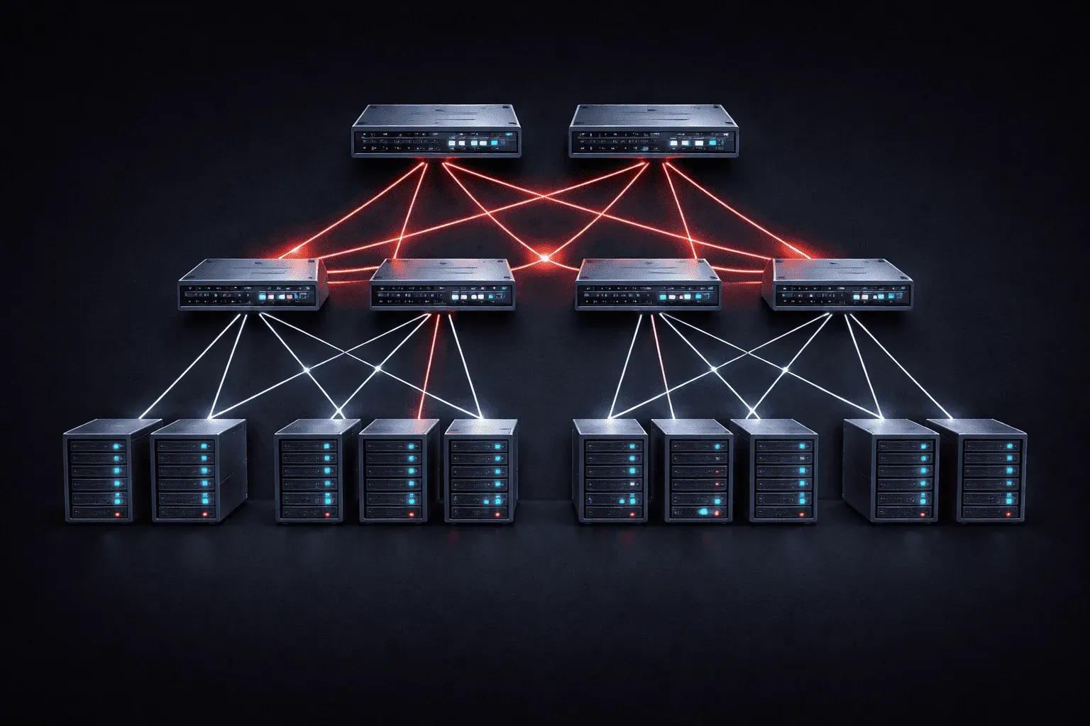
The spine-leaf network architecture has become the gold standard for modern data center designs, replacing traditional three-tier hierarchical networks. If you're studying for your CCNA or working in networking, understanding how to configure this topology is essential. Let's walk through setting up a basic spine-leaf network step by step.
What is Spine-Leaf Architecture?
A spine-leaf network consists of two layers: spine switches (the backbone) and leaf switches (access layer). Every leaf switch connects to every spine switch, creating a non-blocking, high-bandwidth network with predictable latency. This data center topology provides excellent scalability and fault tolerance.
Planning Your Spine-Leaf Setup
Before diving into the network configuration, let's plan our topology:
- 2 spine switches (for redundancy)
- 4 leaf switches (connecting servers)
- Each leaf connects to both spines
- Servers connect only to leaf switches
For this beginner networking example, we'll use basic Layer 3 routing with OSPF to keep things simple. Each device gets a unique OSPF router ID using a loopback-style convention: Spine1 = 1.1.1.1, Spine2 = 2.2.2.2, Leaf1 = 3.3.3.3, Leaf2 = 4.4.4.4, and so on. Router IDs must be unique across the entire OSPF domain.
Step 1: Configure the Spine Switches
Start with your spine switches, which act as the network's backbone. Here's the basic configuration for Spine1:
hostname Spine1
!
interface GigabitEthernet0/1
 description To-Leaf1
 ip address 10.1.1.1 255.255.255.252
 no shutdown
!
interface GigabitEthernet0/2
 description To-Leaf2
 ip address 10.1.2.1 255.255.255.252
 no shutdown
!
interface GigabitEthernet0/3
 description To-Leaf3
 ip address 10.1.3.1 255.255.255.252
 no shutdown
!
interface GigabitEthernet0/4
 description To-Leaf4
 ip address 10.1.4.1 255.255.255.252
 no shutdown
!
router ospf 1
 router-id 1.1.1.1
 network 10.1.0.0 0.0.255.255 area 0
Configure Spine2 similarly, using the next subnet range (10.2.x.x) and router ID 2.2.2.2.
Step 2: Configure the Leaf Switches
Each leaf switch needs connections to both spines and server-facing interfaces. Here's Leaf1's configuration:
hostname Leaf1
!
interface GigabitEthernet0/1
 description To-Spine1
 ip address 10.1.1.2 255.255.255.252
 no shutdown
!
interface GigabitEthernet0/2
 description To-Spine2
 ip address 10.2.1.2 255.255.255.252
 no shutdown
!
interface GigabitEthernet0/3
 description Server-VLAN
 switchport mode access
 switchport access vlan 10
 no shutdown
!
interface vlan 10
 ip address 192.168.10.1 255.255.255.0
!
router ospf 1
 router-id 3.3.3.3
 network 10.1.1.0 0.0.0.3 area 0
 network 10.2.1.0 0.0.0.3 area 0
 network 192.168.10.0 0.0.0.255 area 0
Repeat this process for Leaf2 (router-id 4.4.4.4), Leaf3 (router-id 5.5.5.5), and Leaf4 (router-id 6.6.6.6), adjusting IP addresses and VLANs accordingly.
Step 3: Verify Connectivity
Once configured, verify your spine-leaf network setup is working properly. The neighbor IDs in the output reflect each leaf's OSPF router ID, not the interface IP addresses:
Spine1# show ip ospf neighbor
Neighbor ID     Pri   State           Dead Time   Address         Interface
3.3.3.3           0   FULL/  -        00:00:35    10.1.1.2        Gi0/1
4.4.4.4           0   FULL/  -        00:00:32    10.1.2.2        Gi0/2
5.5.5.5           0   FULL/  -        00:00:38    10.1.3.2        Gi0/3
6.6.6.6           0   FULL/  -        00:00:31    10.1.4.2        Gi0/4
Test end-to-end connectivity by pinging from servers connected to different leaf switches. You should see consistent, low latency paths.
Step 4: Monitor and Troubleshoot
Use these commands to monitor your network:
show ip route- Verify routing tableshow spanning-tree- Check Layer 2 loop prevention on server-facing access portsshow interface status- Verify all links are up
Key Benefits You've Achieved
Your completed spine-leaf architecture provides:
- Predictable latency between any two servers
- High availability through redundant paths
- Easy horizontal scaling by adding more leaf switches
- Simplified troubleshooting with consistent topology
What's Next
Now that you have a basic spine-leaf network running, the next step is exploring advanced features like BGP routing for larger deployments, implementing VXLANs for network virtualization, and adding features like ECMP (Equal Cost Multi-Path) for load balancing across multiple spine switches.
CCNA study resources
- CCNA Official Cert Guide Library (Wendell Odom) — Both volumes covering the full 200-301 exam blueprint. The definitive CCNA study resource.
- Wendell Odom CCNA Vol 1 — Networking fundamentals, switching, VLANs, STP, and IPv4 routing.
- Wendell Odom CCNA Vol 2 — Advanced routing, WAN, security, automation, and network management.