
Common Issues with Network Transceivers and How to Fix Them
This post covers the most common network transceiver issues including incompatibility, dirty fiber connectors, wavelength mismatches, and out-of-range receive power. It provides a practical step-by-step troubleshooting approach with real CLI examples to help learners diagnose and fix transceiver pr

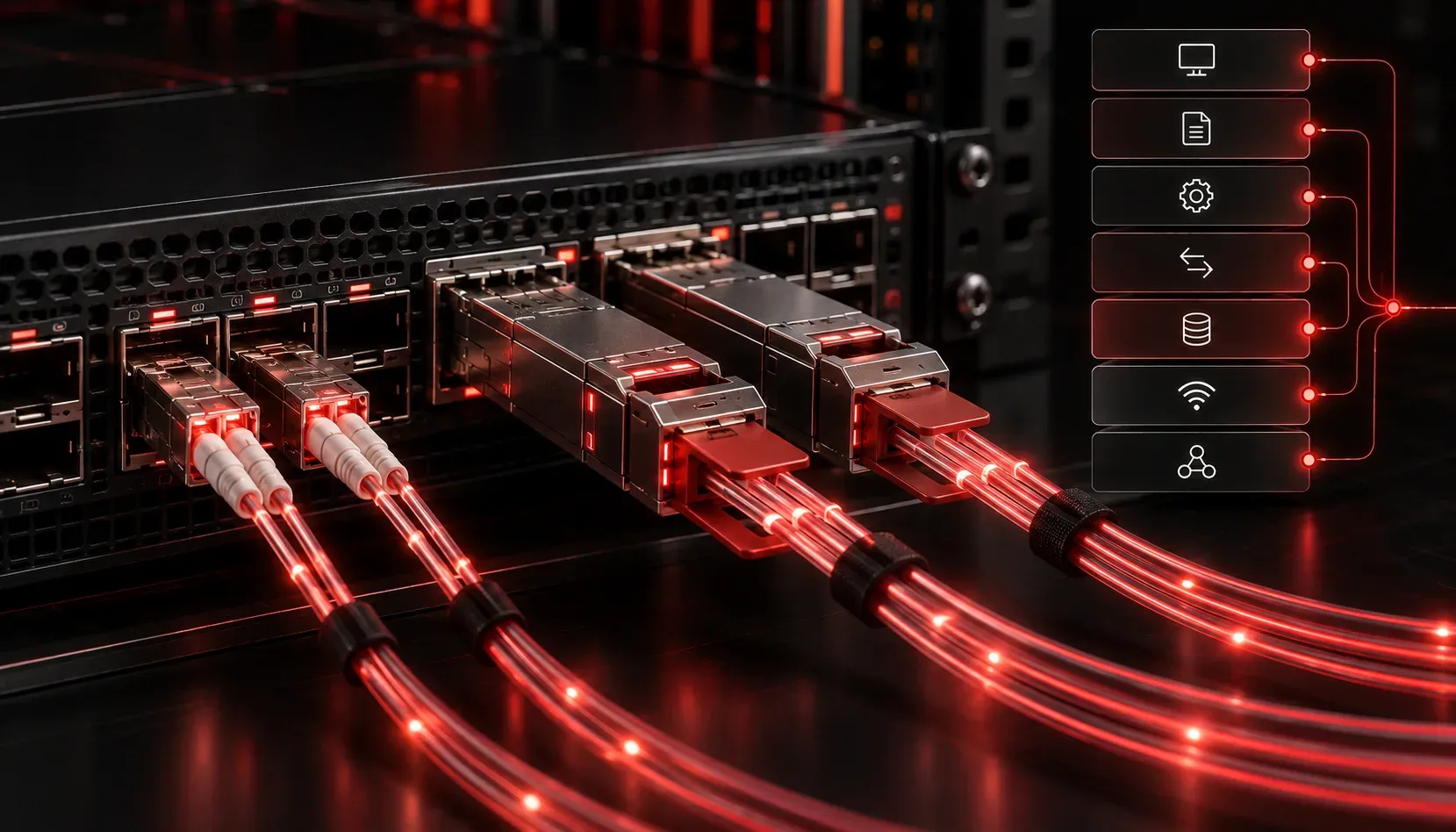
Network transceivers are the unsung heroes of physical network connectivity. They convert electrical signals to optical signals (and back again), allowing devices to communicate across fiber and copper links. When they fail, traffic stops, and the troubleshooting can feel like chasing ghosts. The good news is that most transceiver problems follow predictable patterns, and once you know what to look for, network repair becomes much more straightforward.
What Is a Network Transceiver?
A transceiver is a small, pluggable module that fits into a port on a switch, router, or network interface card. Common form factors include:
- SFP (Small Form-factor Pluggable): Used for 1 Gbps connections over fiber or copper
- SFP+ : Supports 10 Gbps connections
- QSFP/QSFP+: Used for 40 Gbps and 100 Gbps high-density connections
Each transceiver is rated for a specific wavelength, distance, and cable type. Mixing incompatible components is one of the most common sources of transceiver problems.
Common Network Transceiver Issues
1. Incompatible or Unsupported Transceiver
Many enterprise switches, particularly Cisco equipment, use a vendor lock mechanism. If you insert a third-party transceiver, the port may come up with a warning or refuse to operate entirely. You might see a log message like this:
%GBIC_SECURITY_CRYPT-4-VN_DATA_CRC_ERROR: GBIC in port GigabitEthernet0/1 has bad crcTo check what the switch sees, use the show interfaces or show inventory command. If the transceiver is flagged, you may need to enable third-party support (where allowed) or replace it with an approved module.
2. Dirty or Damaged Fiber Connectors
Optical transceivers are extremely sensitive to contamination. A fingerprint or dust particle on a fiber end face can cause significant signal loss or a complete link failure. This is one of the most overlooked transceiver problems in the field.
Before inserting any fiber connector, always clean it with a proper fiber cleaning tool. Inspect the end face using a fiber inspection scope or a USB fiber microscope. A clean connector should have a smooth, unscratched surface with no visible debris in the core area.
3. Wrong Wavelength or Distance Rating
Fiber transceivers are built for specific wavelengths, typically 850nm (multimode, short range) or 1310nm/1550nm (single-mode, long range). Connecting an 850nm transceiver on one end to a 1310nm transceiver on the other will result in no link, even if the cable itself is fine.
Always verify that both ends of a fiber link use matching wavelengths and that the transceiver's distance rating exceeds the actual cable run length.
4. Receive Power Out of Range
Every transceiver has a specified receive power range. Too little light and the link will not establish. Too much light (yes, this happens with short cable runs on high-power transceivers) can also cause errors. On Cisco devices, you can check optical power levels with:
show interfaces GigabitEthernet0/1 transceiverThe output will show transmit and receive power in dBm, along with the acceptable thresholds. If receive power falls outside that range, check for bad connectors, excessive cable length, or incorrect transceiver type.
5. Physical Damage or Overheating
Transceivers can fail simply from age, heat, or physical mishandling. Symptoms include intermittent link drops, high error counters, or a port that comes up briefly and then goes down. Check show interfaces for increasing input errors or CRC errors, which often indicate a failing transceiver or a bad cable.
A Simple Troubleshooting Approach
- Verify the transceiver is seated fully in the port
- Check for compatibility warnings in the switch logs
- Clean and inspect fiber connectors before making any assumptions about hardware failure
- Confirm wavelength and distance ratings match on both ends
- Check optical power levels using diagnostic commands
- Swap the transceiver with a known-good unit to isolate the fault
Following this sequence when you troubleshoot transceivers will eliminate the most common causes quickly and save you from unnecessary hardware replacements.
What's Next
Now that you understand transceiver issues and how to approach network repair at the physical layer, the next step is understanding how cable types, connectors, and physical media standards affect network performance overall. In the next post, we will cover the key cable standards and connector types you need to know for the Network+ exam.
Tools and resources for this topic
- CompTIA Network+ Study Guide — Comprehensive N10-009 exam preparation covering all five domains.