
Blinking vs Solid: Understanding Cisco Link Light Patterns
Learn to interpret Cisco device link lights, understanding the difference between solid and blinking patterns. Solid lights indicate established connections with minimal traffic, while blinking shows active data transmission.

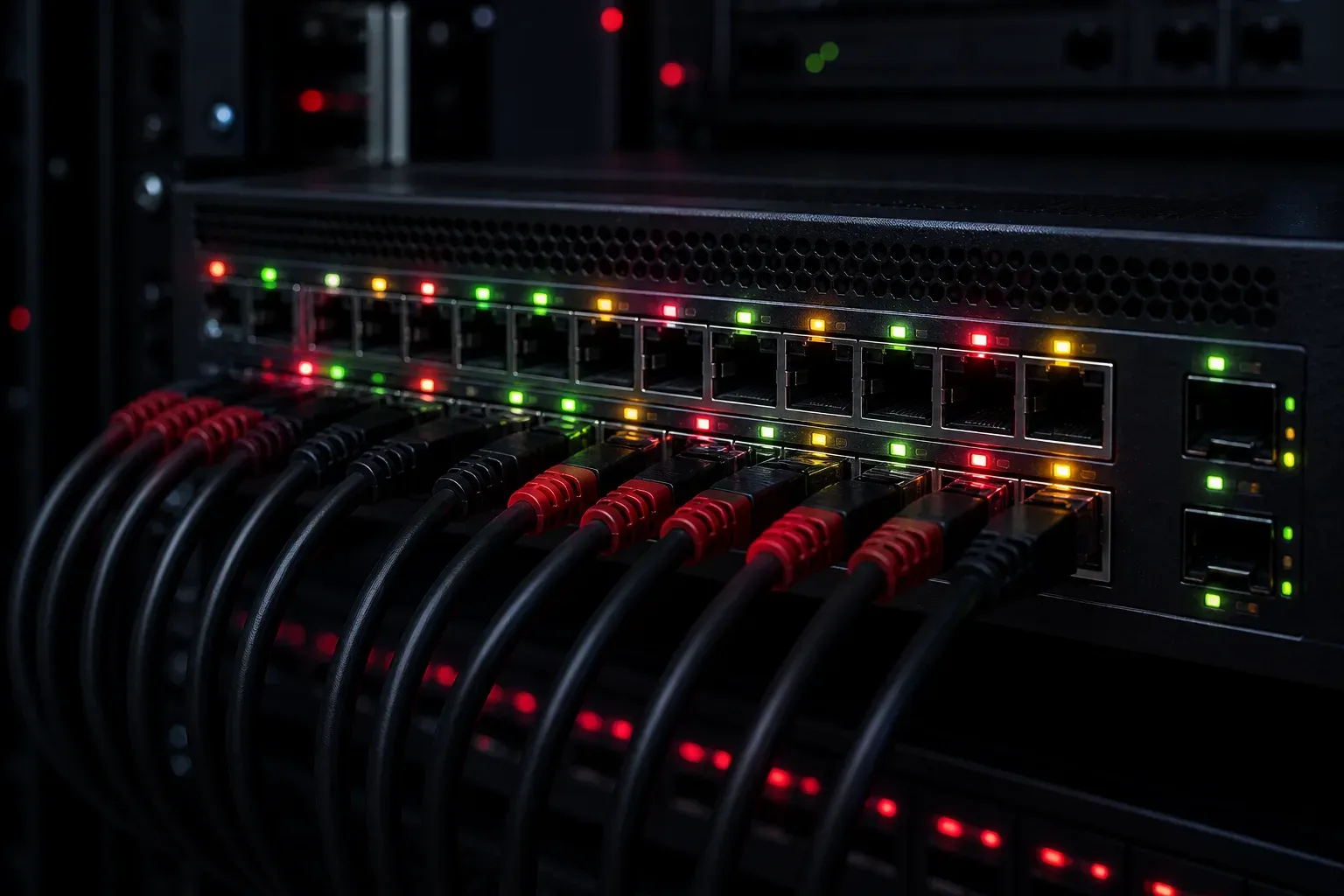
When you're working with Cisco networking equipment, those little lights on your devices aren't just decoration; they're telling you a story about your network's health. Understanding the difference between blinking vs solid link lights is fundamental for anyone getting started with network troubleshooting.
Let's decode what these light patterns mean and how you can use them to quickly assess your network connection status.
What Link Lights Tell You
Link lights, also called LED status indicators, appear on network ports across all Cisco devices, switches, routers, and access points. These lights communicate the operational state of your network connections using color and pattern combinations.
The most common colors you'll encounter are:
- Green: Normal operation
- Amber/Orange: Warning or initialization state
- Red: Error condition
- Off: No link or power
Important: Link light interpretations can vary significantly between different Cisco device models and configurations. Always consult your specific device documentation for accurate status indicator meanings.
Solid vs Blinking: The Key Difference
Solid Link Lights
A solid (steady) light typically indicates that a physical connection has been established, but there's minimal or no data transmission occurring at that moment. Think of it like a phone line that's connected, but nobody's talking.
Common solid light scenarios (examples may vary by device model):
- Solid Green: Good physical link, ready for data transmission
- Solid Amber: Link status varies by device, may indicate initialization, speed negotiation, or operational warnings
- Solid Red: Error condition detected, specific meaning depends on device model
Blinking Link Lights
A blinking (flashing) light shows active data transmission. The frequency of blinking often correlates with the amount of traffic passing through that port. Heavy network activity creates rapid blinking, while light traffic produces slower, more intermittent flashes.
Typical blinking patterns:
- Blinking Green: Active data transmission over a healthy link
- Blinking Amber: Data transmission with potential issues (interpretation varies by device)
- Rapid Blinking: High traffic volume
- Slow Blinking: Low to moderate traffic
Device-Specific Variations
Different Cisco product lines may interpret colors differently:
- Catalyst Switches: Often use green for good links, amber for various warning states
- ISR Routers: May use different color schemes for WAN vs LAN interfaces
- Wireless Access Points: Typically incorporate additional status indicators for wireless functionality
- Nexus Series: May have more complex LED patterns for high-density environments
Reading Cisco Light Patterns in Practice
Let's walk through some real-world scenarios you might encounter during device troubleshooting:
Scenario 1: New Cable Connection
You connect a computer to a switch port. Initially, you might see an amber light (negotiating speed/duplex), followed by a solid green light (link established), and then blinking green when the computer starts sending network traffic.
Scenario 2: No Connectivity Issues
A user reports no internet access. You check the switch port and see no light at all. This immediately tells you there's either no physical connection, a bad cable, or the connected device is powered off.
Scenario 3: Performance Problems
Users complain about slow network speeds. You notice ports showing different colored lights than expected, suggesting potential speed negotiation issues, duplex mismatches, or cable problems.
Quick Troubleshooting with Link Lights
Use this general diagnostic approach (always verify with device-specific documentation):
- No Light: Check physical connections, cable integrity, and device power
- Unexpected Colors: Consult the device manual and check for speed/duplex mismatches
- Solid Lights: Verify if this indicates normal standby or potential issues
- Blinking Patterns: Generally indicate data transmission, observe frequency for traffic levels
Remember that Cisco light patterns vary between device models and firmware versions. The command show interfaces status on switches provides detailed status information that should be used alongside visual indicators.
Pro Tips for Network Monitoring
Beyond basic troubleshooting, link lights help you monitor network health proactively. Ports that suddenly change behavior during business hours might indicate device failures or configuration changes. Unusual blinking patterns outside business hours could signal security issues or misconfigured devices.
Complement visual monitoring with command-line tools:
show interfaces status- Port status summaryshow interfaces [interface]- Detailed interface statisticsshow logging- System logs for interface events
What's Next
Now that you understand basic link light patterns and the importance of device-specific documentation, the next logical step is learning how to correlate visual indicators with command-line interface outputs. We'll cover specific troubleshooting workflows that combine LED status with CLI diagnostics in our next post.