
Interpreting Complex QoS Configurations in Cisco Networks
Advanced techniques for interpreting complex QoS configurations in Cisco enterprise networks, covering hierarchical policies, classification schemes, and systematic troubleshooting approaches. Focuses on real-world scenarios and verification methodologies.

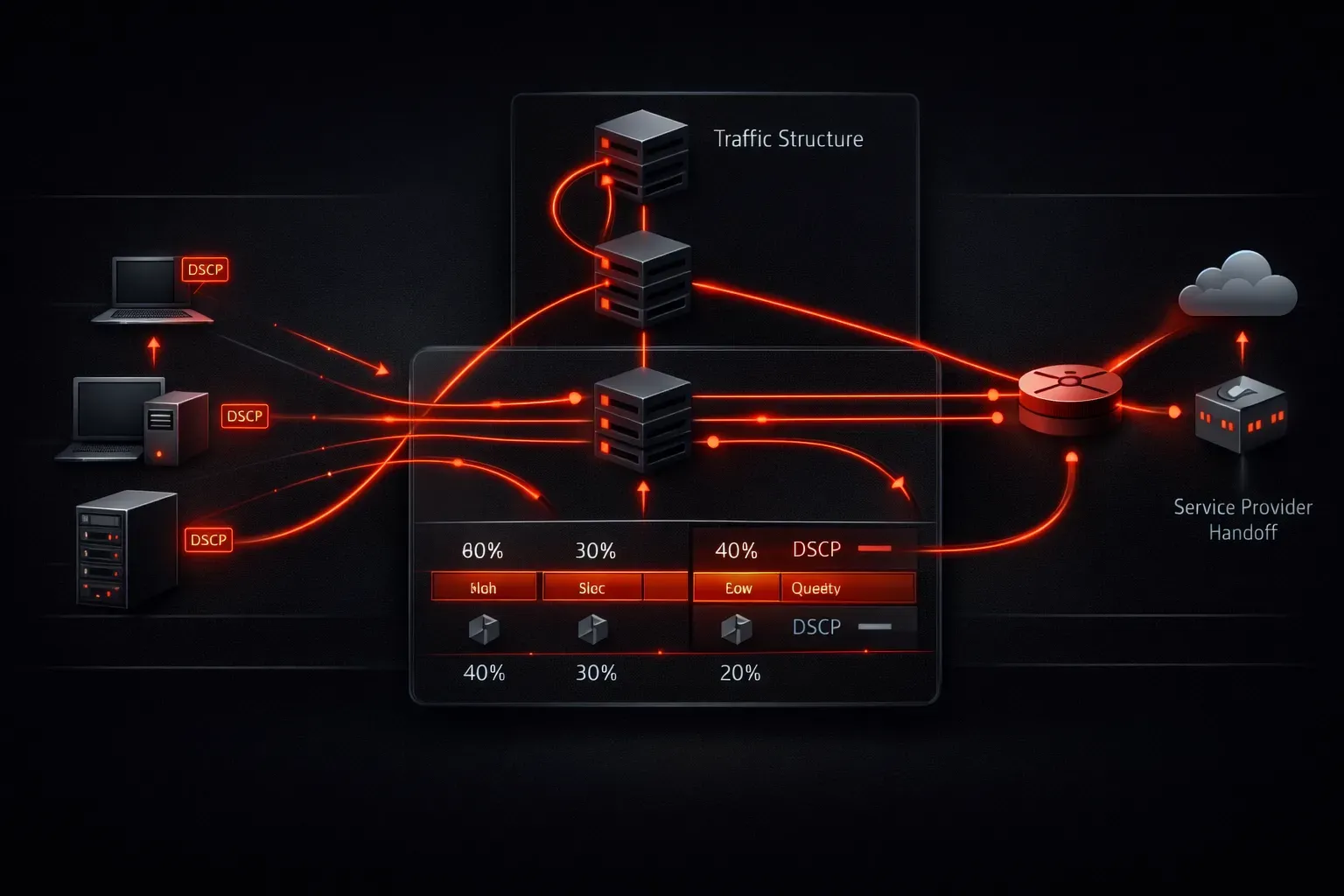
Interpreting complex QoS configurations is a critical skill for network engineers maintaining modern enterprise infrastructures. While basic QoS concepts are foundational, real-world implementations often involve intricate service policies, nested classification schemes, and multi-device coordination that require systematic analysis techniques to understand and troubleshoot effectively.
Understanding QoS Policy Hierarchies
Enterprise QoS implementations frequently employ hierarchical policy structures that can appear overwhelming at first glance. The key to interpreting these configurations lies in understanding the parent-child relationships and traffic flow paths.
Consider this complex hierarchical policy structure commonly found on WAN edge routers:
policy-map BRANCH-EGRESS
 class VOICE-CONTROL
  priority percent 5
 class VOICE-BEARER
  priority percent 20
 class BUSINESS-CRITICAL
  bandwidth percent 30
  random-detect dscp-based
 class BULK-DATA
  bandwidth percent 15
  shape average 50000000
 class class-default
  bandwidth percent 30
  shape average 100000000
When interpreting this configuration, start by identifying the traffic classification criteria referenced by each class. The VOICE-CONTROL and VOICE-BEARER classes likely implement strict priority queuing, while BUSINESS-CRITICAL uses guaranteed bandwidth with WRED for congestion avoidance. The nested shaping on BULK-DATA creates a sub-rate limiting mechanism within the overall interface shaping.
Analyzing Classification and Marking Strategies
Modern enterprise networks implement sophisticated classification schemes that extend beyond simple DSCP marking. Multi-field classification (MFC) policies often combine source/destination addresses, application protocols, and existing QoS markings to create granular traffic categorization.
Examine this enterprise classification policy:
class-map match-any VOICE-CONTROL
 match dscp cs3
 match protocol sip
 match access-group name VOICE-CONTROL-ACL

class-map match-all BUSINESS-APP
 match dscp af31
 match access-group name BUSINESS-SUBNET
 match packet length min 64 max 1500
The match-any logic creates inclusive criteria where traffic matching any condition qualifies for the class. Conversely, match-all requires all conditions to be met simultaneously. Understanding these logical operators is essential when interpreting how traffic flows through the classification hierarchy.
When analyzing marking policies, pay attention to trust boundaries and re-marking behavior:
policy-map TRUST-BOUNDARY
 class UNTRUSTED-SOURCES
  set dscp default
 class TRUSTED-VOICE
  trust dscp
 class class-default
  set dscp af11
Deciphering Service Provider Integration
Enterprise networks connecting to service provider MPLS networks require careful interpretation of QoS hand-off points. Service providers often implement their own QoS models that may not directly align with enterprise marking schemes.
A typical service provider interface configuration might include:
interface GigabitEthernet0/0/1
 description MPLS-Provider-Handoff
 service-policy input PROVIDER-TRUST
 service-policy output ENTERPRISE-EGRESS

policy-map PROVIDER-TRUST
 class class-default
  trust dscp
  police cir 100000000 bc 1875000 be 1875000
   conform-action transmit
   exceed-action set-dscp-transmit af11
   violate-action drop
This configuration demonstrates a trust relationship with DSCP preservation, but implements rate limiting with differentiated actions based on traffic conformance. Non-conforming traffic receives degraded service through DSCP re-marking rather than immediate discard.
Interpreting Queuing and Scheduling Mechanisms
Enterprise switches and routers implement various queuing algorithms that affect traffic behavior during congestion. Understanding the underlying queuing mechanism is crucial for interpreting QoS effectiveness.
On Catalyst switches, examine the queuing configuration:
mls qos map dscp-cos 0 8 16 24 32 40 48 56 to 0
mls qos map dscp-cos 1 9 17 25 33 41 49 57 to 1
mls qos srr-queue output cos-map queue 1 threshold 3 4 5
mls qos srr-queue output cos-map queue 2 threshold 1 0
mls qos srr-queue output cos-map queue 2 threshold 2 1
mls qos srr-queue output cos-map queue 2 threshold 3 2 3
The DSCP-to-CoS mapping defines how Layer 3 markings translate to Layer 2 priority values. The SRR (Shaped Round Robin) queue mappings determine which physical queues handle specific CoS values and their associated drop thresholds.
Troubleshooting QoS Policy Application
When QoS policies don't behave as expected, systematic verification techniques help identify configuration issues. Use show policy-map interface to examine real-time policy statistics:
Router#show policy-map interface gi0/0/1 output

GigabitEthernet0/0/1

  Service-policy output: BRANCH-EGRESS

    Class-map: VOICE-BEARER (match-any)
      5000 packets, 600000 bytes
      5 minute offered rate 12000 bps, drop rate 0000 bps
      Match: dscp ef (46)
        5000 packets, 600000 bytes
        5 minute rate 12000 bps
      Priority: 20% (20000000 bps), burst bytes 500000, b/w exceed drops: 0
This output reveals actual traffic volumes, drop statistics, and bandwidth utilization per class. Zero drops in priority classes indicate adequate provisioning, while drops in lower-priority classes suggest normal QoS behavior during congestion.
Advanced Verification Techniques
Complex QoS deployments benefit from comprehensive verification approaches that extend beyond basic policy statistics. Network engineers should examine end-to-end marking preservation, latency characteristics, and jitter performance.
Use show class-map and show policy-map commands to verify classification logic:
Router#show class-map BUSINESS-CRITICAL
 Class Map match-any BUSINESS-CRITICAL (id 3)
   Match access-group name BUSINESS-APP-ACL
   Match dscp af31 (26)
   Match protocol secure-http
This verification confirms that the class-map correctly references the intended matching criteria and provides the internal class ID for advanced troubleshooting.
What's Next
Understanding QoS configuration interpretation provides the foundation for optimizing traffic prioritization in enterprise networks. The next logical step involves exploring multicast routing protocols and their integration with QoS policies, particularly how IGMP and PIM interact with service policies in complex enterprise topologies.
Tools and resources for this topic
- CCNP ENCOR 350-401 Official Cert Guide — The definitive ENCOR study resource by Brad Edgeworth. Covers enterprise infrastructure, virtualisation, and automation.